Ultra-High-Pressure Y-Type Self-Sealing Globe Valves
Recent advancements in chemical technology have driven more stringent equipment requirements, particularly in temperature, pressure, and corrosion resistance. This paper presents the performance and characteristics of the 4500LB ultra-high-pressure Y-type self-sealing globe valve. In the absence of specific design standards, we analyzed the valve structure and calculated the strength of the self-sealing mechanism according to GB/T 150 standards. The preliminary design was verified using ANSYS strength analysis and CFD fluid simulations. Additionally, a safety pressure-relief design was incorporated during the design phase to ensure reliable operation under extreme conditions, forming the foundation for broader adoption and local manufacturing of ultra-high-pressure Y-type self-sealing globe valves.
In industrial processes such as natural gas-to-acetylene conversion, formaldehyde production, and petroleum refining, certain industrial systems operate under high-temperature, high-pressure, or hydrogen-rich conditions. These environments present significant risks and involve complex operational requirements, making valves crucial components of the pipeline system, especially important. The 4500LB globe valve is typically imported and requires advanced technical specifications and stringent quality standards. Currently, most domestic valve manufacturers have conducted limited research on these valves, and practical applications are scarce. The widely adopted API valve design standards do not define specific design parameters or provide calculation and verification for ultra-high-pressure 4500LB self-sealing valves. Additionally, relevant documentation on these valves is sparse in domestic literature. To stay competitive and secure a leading position in the global market, the domestic valve industry must accelerate their development. This paper explores the design features and reliability aspects of the 4500LB ultra-high-pressure Y-type globe valve.
The selection of globe valves is determined by their intended role within the pipeline system. For general shutoff applications, conventional T-type globe valves are typically used. However, when flow regulation or pressure reduction for improved flow performance is required, Y-type globe valves are preferred. During the design phase, valve performance under actual operating conditions is simulated using 3D modeling software and validated through fluid testing during production. Studies have shown that Y-type globe valves achieve 1.5 to 2 times the flow performance of conventional T-type valves (Figure 1). As a result, Y-type globe valves are frequently used in applications that demand superior flow performance. In pipelines subject to high-temperature, high-pressure, or hydrogen-rich conditions, where operating pressures typically range from 30 to 40 MPa, valves rated at 4500LB are required. The 4500LB valve is designed to operate in demanding environments characterized by high pressures, complex conditions, and stringent safety requirements. To ensure reliable operation, double valves are often installed in series (Figure 2). If one valve fails, the other can be quickly activated, providing a redundant safety mechanism.
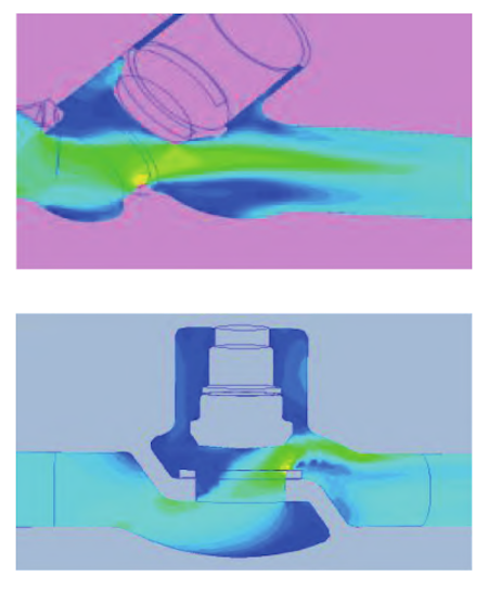
Figure 1 Comparison of Flow Performance Between Y-Type and T-Type Globe Valves
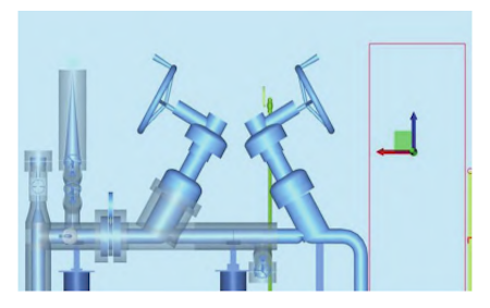
Figure 2 Application of Ultra-High-Pressure Y-Type Self-Sealing Globe Valve
The 4500LB ultra-high-pressure Y-type self-sealing globe valve consists of several key components, including the valve body, valve core, valve bonnet, sealing ring, anti-shear ring, strap, pressure plate, bracket, actuator, and other auxiliary components. As industry standards such as API 600, API 623, API 594, and API 6D do not specify parameters for valves in this pressure class, the design parameters are derived from established standards in the boiler industry, both domestically and internationally. The valve’s temperature and pressure ratings comply with the ASME B16.34 standard. Since the structural length of the 4500LB valve exceeds the ASME B16.10 dimensions, its design is based on the NB-T47044 standard. The valve’s inspection requirements are more stringent than those specified in API 598, and its low-leakage performance must meet the standards set by ISO 15848 and API 624.
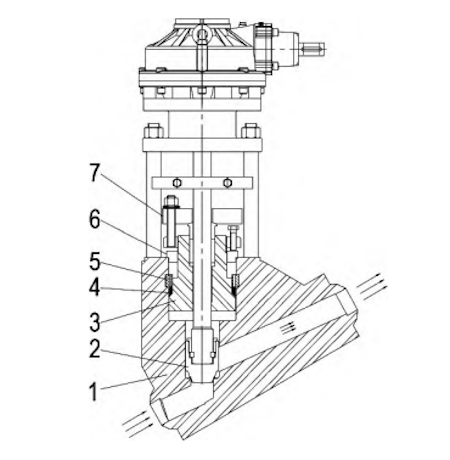
1. Valve body 2. Valve core 3. Valve cover 4. Sealing ring 5. Anti-shear ring 6. Strap 7. Pressure plate
Figure 3 Ultra-High-Pressure Y-Type Self-Sealing Globe Valve
(1) Valve Core Design: The valve core is engineered for precise coaxial alignment with the valve axis to reduce operational force and enhance sealing efficiency. When handling complex media or high-pressure differentials, fluid analysis is employed to determine the optimal structure, preventing component damage, minimizing pipeline vibration, and improving overall system stability.
(2) Valve Body Structure: The valve body is forged, with the flow channel wall thickness complying with ASME B16.34 Table 3A22. The wall thickness of the middle cavity matches that of the flow channel, and the overall design complies with API 600-1997 standards. The design of the 4500LB ultra-high-pressure valve incorporates an increased safety margin for component strength.
(3) Valve Bonnet Design: The valve bonnet is designed in accordance with GB/T150, with longitudinal bending stress subjected to analysis and optimization, as shown in the accompanying figure.
(4) Sealing Surface Treatment: The sealing ring is welded with 300-series stainless steel, in accordance with MSS SP-144 standards, to improve sealing performance and extend service life.
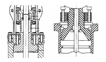
Figure 4 API 600-1997 Figure A-1
During operation, when the valve core shifts to the middle cavity position, a closed cavity, referred to as cavity A, forms between the valve core and valve body, as shown in Figure 5. If the pressure or medium in cavity A is not effectively relieved as the valve continues to open, this may lead to difficulty in operation, requiring excessive force and potentially causing incomplete opening, vibration, or abnormal noise in the valve core. For high-pressure 4500LB valves, the risk of pressure retention in the valve cavity must be carefully controlled. The design process should incorporate features designed to address the specific operating conditions of the pipeline medium.
For valves that are already installed in pipelines and cannot be replaced, pressure relief can be accomplished by halting the system, opening the valve (as shown in Figure 6), and welding in a bypass pipe. After welding, heat treatment is applied to relieve stress and ensure the quality of the weld. This procedure enables the discharge of medium or pressure in cavity A during normal pipeline operation, ensuring the smooth and safe function of the Y-type ultra-high-pressure self-sealing globe valve. Considering the interaction between the valve core and valve body, pressure relief schemes for the closed cavity should be integrated during the early design stage to ensure effective pressure relief within the valve cavity, reducing safety risks to the pipeline. Different pressure-relief designs yield varying flow characteristics. Fluid analysis, based on the valve specifications, is critical for selecting a low-pressure-drop design and ensuring the safe, high-performance operation of the valve cavity flow channel.
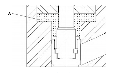
Figure 5 Closed Cavity

Figure 6 Schematic of Bypass Channel, Pressure Relief Hole, and Lace Valve Core
Historically, domestic petrochemical plants relied on imported 4500LB ultra-high-pressure self-sealing globe valves due to limited expertise and the absence of documented design verification processes among Chinese manufacturers. After the valve design is developed based on the proposed approach, it undergoes strength analysis using ANSYS simulation software and fluid analysis via CFD. The results of these verifications are shown in Figure 7. Valve designs are typically classified into conventional and analytical designs. The latter includes elastic stress analysis, limit load analysis, and elastic-plastic stress analysis, of which elastic stress analysis is the most commonly used. This method classifies stress into primary, secondary, and peak categories, each with distinct evaluation criteria. Compared to conventional design, this method often yields more cost-effective equipment. However, it has certain limitations:
(1) While generally reliable, it may not offer adequate safety margins for certain structures.
(2) It necessitates advanced technical expertise in stress analysis. Differences in judgment regarding positions and stress categorization among engineers can lead to inconsistent results. Misclassifying primary stress as secondary stress could lead to unsafe designs.
The complexity of the Y-shaped flow channel structure makes it difficult to evaluate primary and secondary stresses. The limit load method provides a more accurate analysis and minimizes the risk of misclassification. This method offers an alternative to traditional stress analysis by eliminating the need for primary stress evaluation and directly assessing equilibrium conditions at the ultimate limit state.
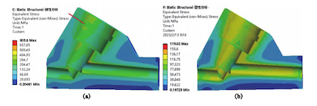
Figure 7 Elastic analysis and plastic analysis
The friction coefficient of the sealing surface significantly impacts valve torque. Reducing this coefficient effectively reduces the operating force needed to open or close the valve. To meet operational requirements, high-performance grinding equipment should be selected. Additionally, the components used in the self-sealing globe valve must meet higher safety standards. After assembly, the valve is subjected to a rigorous inspection process. The sealing test exceeds API 598 requirements, ensuring zero leakage and 100% sealing, surpassing current valve inspection standards. The valve must also meet the low-leakage sealing requirements specified in ISO 15848 and API 624. The low-leakage detection system is illustrated in Figure 8.
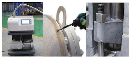
Figure 8 Low leakage detection device
In traditional valve design, as pressure increases and cavity size expands, wall thickness typically increases. Designing an ultra-high-pressure Y-type self-sealing globe valve using traditional methods would result in an excessively large and cumbersome valve body, classifying the valve as a specialized component. Critical components are fabricated from high-strength, corrosion-resistant materials such as XM-19, ASTM A638 660, and nickel-based alloys. The corrosion resistance of smaller components in contact with the medium must equal or exceed that of the valve body. Additionally, the valve core and reverse seal are welded with corrosion- and wear-resistant sealing surfaces, with cemented carbide used for the sealing surface. The thickness of the welded cemented carbide exceeds that of standard valves, with an alloy layer thickness of approximately 3 mm and a pure alloy thickness of at least 1.6 mm. For valves operating under high-pressure differentials, the medium can cause significant erosion of the valve core surface, potentially leading to valve leakage. Valves operating under such conditions require enhanced surface hardening treatments or specialized valve core designs to resist erosion.
Coaxiality of components is a critical factor influencing the sealing performance and operating force of the ultra-high-pressure Y-type self-sealing globe valve. Coaxiality of key components, such as the valve core, valve body cavity, stuffing box, and drive sleeve, is crucial. To minimize the impact of coaxiality errors, specific tooling is used, and part mismatching is minimized. The sealing surfaces, from the valve core to the valve body sealing ring, are processed using a 'single-step forming' method. This ensures that coaxiality remains within design specifications, utilizing the same tooling and positioning reference.
The technical standards for valves used in high-risk applications, such as those subjected to high temperatures and pressures, are stricter than those for general high-pressure valves. In many cases, selecting the appropriate valve cavity structure and optimizing the component layout can improve flow efficiency, resulting in a more cost-effective design for the ultra-high-pressure Y-type self-sealing globe valve. The design must address the various safety risks associated with real-world use and incorporate necessary modifications to mitigate potential pressure fluctuations.
For design verification of the ultra-high-pressure self-sealing globe valve, ANSYS and CFD simulations are essential for ensuring valve safety when pressures exceed reference standards. By incorporating high-efficiency, high-precision automation equipment into the production process, improving the surface finish of the valve core sealing surface, and reducing the friction coefficient, the valve operating force can be significantly decreased, making the ultra-high-pressure Y-type self-sealing globe valve easier to operate and more labor-efficient.


