Typical Structural Design of Ultra-Low Temperature Ball Valves
On this page
1. Overview
As one of the most promising clean energy sources of the 21st century, natural gas has consistently shown strong market potential. According to the medium and long-term natural gas demand forecast report released by the International Energy Agency (IEA), global demand for natural gas (hereinafter referred to as LNG) is expected to reach 5.1 trillion cubic meters by 2035, accounting for 25% of global energy demand. Ultra-low temperature valves are critical control components in LNG pipeline transportation, and their demand has increased significantly in recent years with the growth of receiving stations. Since the actual transportation temperature of LNG after liquefaction is extremely low, reaching -162°C, valves can only be tested under simulated working conditions at the factory. These tests do not fully reflect the actual performance of the valves in operation, making it essential to combine field experience with targeted optimization design.
2. Typical Structure
2.1 Design of Drainage Groove on the Top of the Extension Sleeve
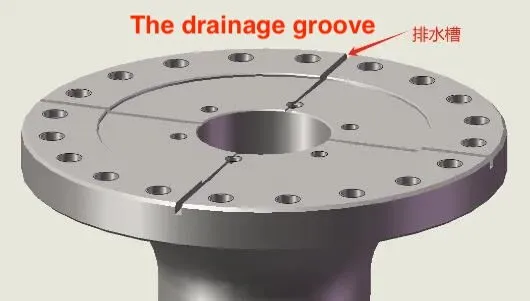
To prevent the packing position of the low-temperature valve from freezing, all valve types except check valves, whether cold box type or non-cold box type, are generally designed with an extended valve cover (referred to as an extension sleeve), with a specified minimum extension height as outlined in relevant standards. At the project site, the low-temperature medium flows through the valve cavity, causing normal frost to form on the outside of the valve body due to heat transfer, which results in a relatively low ambient temperature near the valve body. Water vapor in the air will liquefy when cooled, and the resulting condensate will naturally flow down the bracket. Upon reaching the top of the extension sleeve, it can easily seep into the packing cavity. Over time, this can cause the inner wall of the extension sleeve to freeze, leading to valve jamming and other malfunctions. To prevent this issue, several drainage grooves with a 5° downward angle were designed at the top of the extension sleeve, based on field experience, as shown in Figure 1. When condensate reaches the platform at the top of the extension sleeve, it can flow out smoothly along the 5° downward-sloping grooves, preventing accumulation and seepage into the packing cavity, thereby avoiding potential hazards. In practice, this drainage groove structure is mainly used in designs with larger diameters, as the localized grooves maintain the overall strength of the connecting plate at the top of the extension sleeve. Additionally, for valves with larger diameters, the tops typically need to connect to the bracket and actuator to ensure proper alignment and stability of the mechanical transmission. For smaller diameter valves operated by a handle, to save processing time and simplify the process, the downward drainage grooves can be replaced with a full circle of inclined end faces, and the original flat end faces can be directly shaped into an outward draft form during processing. When condensate reaches the plane, it can flow out in any direction, saving the milling process and achieving the same effect.

Figure 1 The drainage groove design on the top of the extended sleeve

Figure 1 The drainage groove design on the top of the extended sleeve
2.2 Stuffing Box Design
Most media flowing through cryogenic valves are high-risk, especially substances like LNG. As the temperature rises, the volume expands significantly. If leakage occurs, it can easily create a significant fire hazard. Therefore, leakage is unacceptable for this type of valve. This has always been a challenge for maintaining dynamic sealing at the valve stem position. Many manufacturers ensure their products' sealing performance at the factory, and they can even pass low-leakage detection smoothly. However, as a force transmission component, the valve stem either performs lifting or rotating movements, and the packing is affected by the valve's opening and closing, causing movement of the refrigerant medium. This leads to significant temperature changes, resulting in unstable thermal expansion and contraction of the seal. This issue has consistently challenged the long-term sealing performance of the packing.
Additionally, cryogenic valves are generally designed with extended valve necks, except for check valves. The height of the extended valve neck increases as the operating temperature decreases. Typically, the height of the valve neck in ultra-low temperature valves is not less than 250mm, and processing errors in parts like valve stems and extended valve necks are inevitable. As a result, the valve stem and stuffing box are often not concentric during assembly. In conventional designs, the valve stem is forced back into the concentric position by relying on the packing gasket and packing gland. Although this method may appear unchanged externally, the valve switching torque becomes abnormally large during actual use. Sometimes, the required operating force exceeds the torque that the valve stem can handle, seriously affecting the valve's service life. In response to these issues, the following design scheme is proposed, as shown in Figure 2.

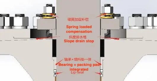
Figure 2 The combined seal structure design of the stuffing box
The combined design of the stuffing box includes a Lip-seal as the main seal, an integrated bearing packing pad, combined packing (typically a graphite and PTFE combination), and disc spring-loaded compensation from bottom to top. The Lip-seal, acting as the main seal, is closest to the medium pressure side and plays a crucial role. Additionally, the packing pad design has been improved. The conventional packing pad and bearing are combined into a T-shaped integrated design, which aligns well with bearing requirements and compensates for the non-concentricity between the valve stem and the stuffing box at the extended valve neck position. The top T-shaped step precisely controls the sealing space required by the Lip-seal below, effectively preventing pressure buildup and potential damage from squeezing the Lip-seal. The packing consists of two materials that serve as an auxiliary seal. In this context, graphite is primarily used for fire prevention, while PTFE serves as the auxiliary seal. The primary reason graphite is not used as the auxiliary seal here is to reduce the switching torque. The top packing gland incorporates a disc spring to provide preload. Typically, two pairs of four disc springs are selected and installed face to face. This combination not only ensures effective sealing but also maintains the coaxiality of the valve stem and extension sleeve, effectively controls torque, and delivers reliable performance.
Additionally, cryogenic valves are generally designed with extended valve necks, except for check valves. The height of the extended valve neck increases as the operating temperature decreases. Typically, the height of the valve neck in ultra-low temperature valves is not less than 250mm, and processing errors in parts like valve stems and extended valve necks are inevitable. As a result, the valve stem and stuffing box are often not concentric during assembly. In conventional designs, the valve stem is forced back into the concentric position by relying on the packing gasket and packing gland. Although this method may appear unchanged externally, the valve switching torque becomes abnormally large during actual use. Sometimes, the required operating force exceeds the torque that the valve stem can handle, seriously affecting the valve's service life. In response to these issues, the following design scheme is proposed, as shown in Figure 2.

Figure 2 The combined seal structure design of the stuffing box
The combined design of the stuffing box includes a Lip-seal as the main seal, an integrated bearing packing pad, combined packing (typically a graphite and PTFE combination), and disc spring-loaded compensation from bottom to top. The Lip-seal, acting as the main seal, is closest to the medium pressure side and plays a crucial role. Additionally, the packing pad design has been improved. The conventional packing pad and bearing are combined into a T-shaped integrated design, which aligns well with bearing requirements and compensates for the non-concentricity between the valve stem and the stuffing box at the extended valve neck position. The top T-shaped step precisely controls the sealing space required by the Lip-seal below, effectively preventing pressure buildup and potential damage from squeezing the Lip-seal. The packing consists of two materials that serve as an auxiliary seal. In this context, graphite is primarily used for fire prevention, while PTFE serves as the auxiliary seal. The primary reason graphite is not used as the auxiliary seal here is to reduce the switching torque. The top packing gland incorporates a disc spring to provide preload. Typically, two pairs of four disc springs are selected and installed face to face. This combination not only ensures effective sealing but also maintains the coaxiality of the valve stem and extension sleeve, effectively controls torque, and delivers reliable performance.


