Structure of Cryogenic Top-Entry Ball Valves for LNG Receiving Stations
Abstract
This paper provides an overview of commonly used sealing structures in cryogenic top-entry ball valves for LNG receiving stations. It examines the pressure capacity, operational characteristics, and failure mechanisms of different valve structures within the operating system. The paper further analyzes the design of the top-entry ball valve. Additionally, it investigates the effects of thermal stress at pipeline connection points of the ball valve under varying temperatures, as well as the failure of flange joint seals. Finally, the paper explores the reasons for eliminating flange-end connections in LNG cryogenic pipeline valves.
1. Overview
Natural gas is recognized as an efficient and clean energy source, valued for its low emissions and abundant reserves. LNG receiving stations have experienced rapid growth. CNOOC is expected to construct 15 to 17 LNG receiving stations by 2030, with cryogenic top-entry ball valves playing a key role in regulating cryogenic fluids in these facilities. Cryogenic top-entry ball valves currently represent more than 80% of all cryogenic valves used in LNG receiving stations. Currently, there is significant variation in the structural designs of these valves across LNG stations. This article analyzes the structural designs of various cryogenic top-entry ball valves, examines their functional characteristics and potential risks, and offers recommendations for product design, manufacturing, and engineering selection.
2. Valve Connection End Analysis
During LNG operations, pipelines are typically not fully filled, creating a temperature difference between the upper and lower sections of the liquid surface. The upper section remains warmer than the lower section. When flange-end connections are used, differences in the tightening force of the bolts above and below the liquid surface can result in uneven stress on the flange joint seal, increasing the risk of leakage. Additionally, as the pipeline is not fully filled, the linear expansion coefficient of the material varies with temperature. The warmer upper section shrinks less than the cooler lower section, causing the upper section to form an arc after prolonged operation (Figure 1). The stress from this arc can cause flange joint seal failure. Given LNG's highly flammable and volatile nature, maintaining the integrity of the valve's pressure boundary is critical, and flange joint failure must be effectively mitigated. As a result, cryogenic ball valves in LNG receiving stations generally employ butt-welded connections rather than flange-end connections.
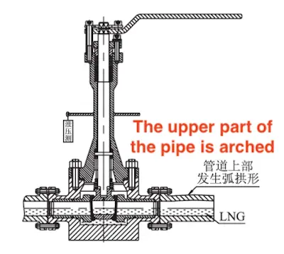
Figure 1 Failure mechanism of the top-mounted ball valve with flange-end connections
3. Analysis of Top-mounted Structure
The top-mounted structure of cryogenic ball valves in LNG receiving stations is designed primarily to enable online inspection and maintenance. However, analysis of domestic LNG receiving stations shows that cryogenic top-mounted ball valves at the outlets of certain high-pressure pumps have failed due to pump vibrations and other factors, causing gasket failure between the valve body and cover, often leading to leakage. In such cases, when a leakage alarm is triggered, the cold insulation layer is removed, and the connecting bolts between the valve body and cover are tightened to prevent further leakage. Cryogenic pipelines do not include a maintenance bypass during installation. Establishing a maintenance bypass can cause gas blockage, presenting significant challenges and risks during pipeline re-cooling and preventing valve isolation for online maintenance. Furthermore, even if online maintenance is feasible, the valve must undergo a strength test at 1.5 times its cold working pressure (CWP) after reassembly to confirm flange joint integrity. However, conducting this test onsite is generally impractical. Additionally, detecting small leaks in the middle flange gasket and packing of cryogenic top-mounted ball valves is neither straightforward nor cost-effective.
Testing and analysis show that the primary purpose of the top-mounted structure is to maintain the integrity of the pressure-bearing boundary, rather than to enable online maintenance. If a ball valve employs a side-mounted structure, the valve body must be bolted together. Flange connections in side-mounted ball valves present a similar risk of failure, potentially compromising the sealing integrity of the combined valve body. Alternating temperature stresses can loosen the connecting bolts in side-mounted ball valves, resulting in flange joint seal failure. Therefore, cryogenic ball valves in LNG receiving station pipelines must utilize a top-mounted structure.
At high-pressure pump outlets, cryogenic top-mounted ball valves typically employ only a single-end face sealing structure with a spiral-wound gasket between the valve body and cover. The lack of anti-loosening measures for bolts often results in flange joint seal failure. It is recommended to adopt a double-sealing structure that includes a pan-plug radial seal and a spiral-wound gasket end-face seal between the valve body and bonnet (Figure 2). Additionally, JB/ZQ 4342 double-sided knurled disc washers must be installed on the bolts to prevent loosening caused by pump vibrations and alternating temperature loads, ensuring reliable sealing of the middle flange joint.
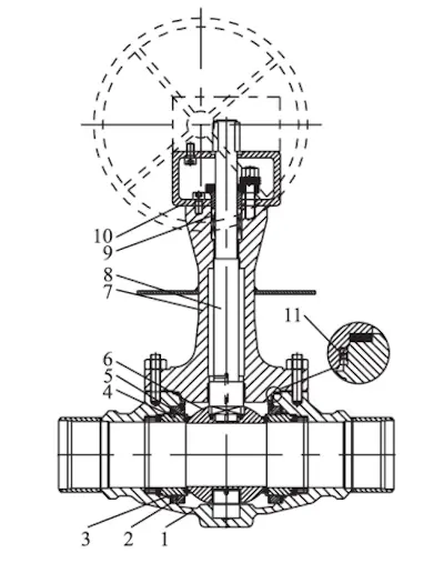
1. Valve body 2. Valve seat holder 3 and 11. Pan plug seal 4. Valve seat 5. Soft seated
6. Ball 7. Valve bonnet 8. Valve stem 9. Packing 10. Electrical installation
Figure 2 Pan plug sealing structure with double seal between valve body and valve bonnet of Top-mounted trunnion ball valve
4. Ball Valve Sealing Structure
Cryogenic top-mounted ball valves used in LNG receiving stations can be designed with either a floating ball or a fixed ball structure, depending on the pressure and specifications. The trunnion ball valve structure typically includes the globe valve and the hemispherical eccentric ball valve. The sealing structures of the globe valve include a pan plug seal, a bellows seal, and a metal diaphragm seal, each positioned between the valve seat and the ball or valve body.
4.1 Pan-Seal Structure
The pan-seal structure is positioned between the valve body and the valve seat of the cryogenic top-entry ball valve (Figure 3). This sealing mechanism requires precise machining and a smooth surface finish on the mating components to ensure effective sealing. Adhering to proper assembly protocols is critical to preventing seal failure. In top-entry valve designs, the valve seat holder moves reciprocally during ball installation. This movement assists in placing the ball, resetting the sealing ring, and ensuring consistent contact between the ball and the valve seat. Accordingly, the contact surface between the pan-seal and the valve seat holder must be engineered to withstand frictional forces during operation. Due to the interference fit between the pan-seal and the valve seat holder, wear may occur during the reciprocating movement of the valve seat holder. Over time, this wear can compromise the sealing performance of the pan-seal at cryogenic temperatures. For valves employing a unidirectional pan-seal structure on the left end, if the pressure in the middle cavity does not exceed the threshold required to push the valve seat away from the ball and achieve pan-seal discharge, pressure will instead escape through the pan-seal. Valve pressure relief cannot typically be achieved using a universal plug, as depressurization prevents the plug from reliably resealing. This limitation poses a risk of inconsistent sealing and operational failure.
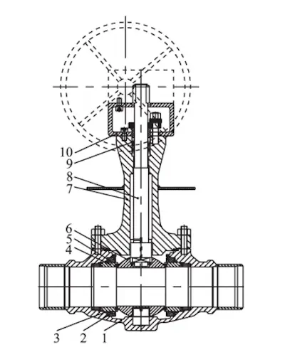
1. Valve body 2. Valve seat holder 3 and 11. Pan plug seal 4. Valve seat 5. Soft seated
6. Ball 7. Valve bonnet 8. Valve stem 9. Packing 10. Electrical installation
Figure 3 Pan plug sealing structure of Top-mounted trunnion ball valve
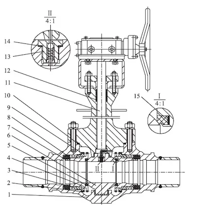
1. Valve body 2. Threaded guide sleeve 3. Bellows 4. Valve seat 5. Seal ring
6. Ball 7. Spring seat 8. Spring mirror 9,10,14 and15. Gasket
11. Valve stem 12. Packing group 13. Pressure relief valve
Figure 4 Bellows seal top entry trunnion ball valve
4.2 Bellows Sealing Structure
The metal bellows sealing structure, positioned between the valve body and seat of the cryogenic top-entry ball valve (Figure 4), replaces the traditional radial seal with a combination of bellows and a wound gasket end-face sealing system, enhancing sealing reliability. However, this structure is limited to a DBB (Double Block and Bleed) arrangement, which does not fulfill the DIB-1 (Double Isolation and Bleed) requirements necessary for certain operational systems. Bellows are typically designed to withstand external pressure, but during valve operation, the working fluid may infiltrate the bellows, subjecting it to internal pressure as well. This dual pressure scenario increases the risk of mechanical failure. Moreover, the current manufacturing range for bellows sealing structures (up to 6 inches, 1500 lbs) does not align with the dimensional and pressure specifications required for LNG receiving station ball valves.
4.3 Metal Diaphragm Sealing Structure
The metal diaphragm sealing structure, also located between the valve body and seat of the cryogenic top-entry ball valve (Figure 5), enhances sealing performance through its robust design. However, similar to the bellows structure, it is restricted to a DBB configuration, which fails to meet the DIB-1 requirements essential for certain operational applications.
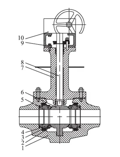
1. Valve body 2. Valve seat lock ring 3. Sealing valve seat 4. Valve seat support ring 5. Spring-loaded seat 6. Ball 7. Valve bonnet 8. Valve stem 9. Bracket 10. Electrical installation
Figure 5 Metal diaphragm seal top-mounted trunnion ball valve
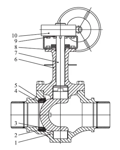
1. Valve body 2. Valve seat 3. Front valve seat 4. Rear valve seat 5. Valve seat adjuster
6. Valve bonnet 7. Valve stem 8. Packing 9. Packing sleeve 10. Electrical installation
Figure 6 Top-mounted eccentric hemispherical ball valve
Point out any major mistake that make it not authentic business english, and put the revised paragraph with the title at the end.
4.4 Eccentric Hemispherical Valve Structure
Based on structural analysis of several existing cryogenic top-mounted ball valves, the eccentric hemispherical ball valve was developed with a double-eccentric design to mitigate potential failure modes (Figure 6). This design ensures progressive contact during closure, significantly reducing friction torque between the ball and sealing ring, which is a common issue in traditional cryogenic top-mounted ball valves. Compared to standard cryogenic top-entry ball valves with similar specifications, this design results in lower operating torque and reduces wear on the sealing ring, thereby extending the valve's service life, particularly in applications requiring frequent operation. Additionally, the design eliminates the middle cavity, preventing fluid accumulation and addressing risks associated with such accumulation, as well as the improper installation of the pressure relief end found in traditional cryogenic top-entry ball valves. The top-mounted eccentric hemispherical ball valve provides bidirectional sealing, although further testing is needed under high-pressure conditions.
5. Conclusion
This analysis examines the rationale for using welded ends and top-entry structures in ball valves at LNG receiving stations, along with the structural characteristics of various existing top-entry cryogenic trunnion ball valves. It also highlights the potential risks associated with different valve designs. The primary objective is to offer guidance on the design, manufacturing, and engineering selection of valves to mitigate risks and ensure the safe and reliable operation of cryogenic top-entry ball valves in LNG receiving stations.


