Problems in the Distribution of Coating Hardness of Ball Valve Cores
1. Overview
A ball valve is one of the most important valves in the process industry. The medium pressure difference it allows to pass through is great, and it can be used in a wide range of environments. It is favored by petroleum and chemical companies. The ball core is the core part of the ball valve, and the quality of the ball core is positively correlated with the service life of the ball valve. Enterprises usually use the vacuum cladding process to clad nickel-based self-fluxing alloy coating on the surface of the ball core, which greatly improves the wear resistance and corrosion resistance of the ball core and reduces production costs. In the production process of the ball valve, the processing process of the ball core is complicated, and the process requirements are extremely high, and strict regulations are put forward on the thickness, hardness, porosity, and surface roughness of the coating to ensure the quality of the ball core coating. The coating preparation process and the grinding process are the two links most prone to problems of the ball core when it is processed. To solve the problem of non-uniform hardness distribution that occurs frequently in the core in this process, 8 ball cores in the same batch were taken as the research object and the processes are tracked, recorded and summarized, improving the output rate of the qualified ball core.
2. The testing processes
The process of quality tracking test on the ball core includes pretreatment of cores, flame spraying, vacuum cladding, core marking, inspection of cores, grinding, and quality inspection of cores.
2.1 The pretreatment of the core
The core is made from stainless steel 316. To improve the deposition efficiency and bonding strength of the powder during the flame spraying of the core, the core is pretreated by sandblasting to remove oil and oxides on the surface of the core and increase the surface roughness. The blasting pressure is 0.8MPa; the air flow rate is 5 m3/h, and brown corundum sand grains (0.1 to 2mm) are used.
2.2 Flame spraying and vacuum cladding
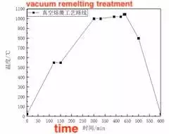
The coating powder is Ni60A special powder for vacuum cladding produced by Alloy Powder Factory of Lanzhou University of Technology. The particle size of the powder is about 100μm. The specific composition is shown in Table 1. After sandblasting, use an oxyacetylene flame spray gun for flame spraying. The flame spraying coating has a high porosity; the bonding with the substrate is mechanical bonding, and the bonding strength is low. It cannot meet the requirements for the valve in a high-pressure corrosion environment. Vacuum remelting treatment is carried out on the coating, and the process route of vacuum remelting treatment is shown in Figure 1.

Figure 1 The vacuum remelting treatment
In the remelting process, when the furnace temperature reaches the melting point, the elements are fully diffused, and the precipitated phase has obvious rules, which can greatly reduce the porosity of the coating. When the coating melts, elements diffuse with the surface of the substrate, and the bonding method between the coating and the substrate changes from mechanical bonding to metallurgical bonding, which greatly enhances the bonding strength between the substrate and the coating. During vacuum cladding, the runner opening of the ball core is placed parallel to the furnace, and after the furnace temperature rises to the melting point of the powder, a flow point will be formed on the bottom of the ball core due to the influence of the coating. As shown in Figure 2, this point is relatively protruding and will have a certain influence on the grinding process.

Figure 2 The schematic diagram of the flow point of the ball core
2.3 Detection of ball cores
The sphericity, maximum deviation and diameter after cladding were tested with a three-coordinate detector, and the test results are shown in Table 2. According to the core diameter, the 8 ball cores were divided into 3 groups for analysis.
2.4 Marking the ball core
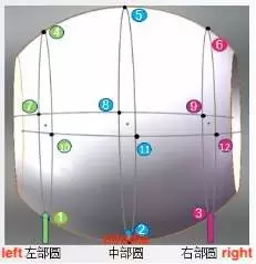
Before the ball core is ground, mark the positioning point of the ball core, as shown in Figure 3. Define that there are three circles in the core near the top of the runner opening, the middle of the runner opening and the bottom of the runner opening, which are recorded as the left circle, the middle circle, and the right circle. The marking points on the left circle are 1, 4, 7 and 10; the marking points on the middle circle are 2, 5, 8 and 11; the marking points on the right circle are 3, 6, 9 and 12. Mark 1, 2, 3 on the bottom surface near the furnace, 4, 5, 6 on the symmetrical surface, 7, 8, 9 and 10, 11, 12 on the left and right sides. Among them, 2 is the position of the flow point of the ball core, and these 12 points can reflect the entire grinding situation of the ball core surface. Track the 8 ball cores and record the grinding at each anchor point. The corresponding direction should be marked in the runner mouth to find out the approximate position of each positioning point after grinding.

Figure 3 Marking the core positioning point
2.5 Grinding
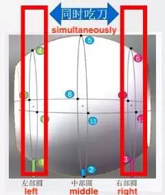
When grinding, the ball core is first aligned, and the axial alignment and cutterhead alignment are performed based on the surface of the ball core. When grinding, try to ensure that all the positioning points on the left circle and the right circle are engaged by the knife, as shown in Figure 4. The grinding time involved in this article is the total time from the start of grinding the positioning points to the grinding of all the positioning points. Table 3 shows the grinding processing data of the 8 ball cores tracked. Among them, the flow point of the 2#, 3# and 7# ball cores is relatively large, which may affect the total grinding process. Therefore, after 20 minutes and 40 minutes of grinding, the cutterheads of 2# and 7# ball cores were adjusted from right to left and from left to right by 60μm and 50μm, while the grinding process of 3# ball cores is not adjusted.

Figure 4 The schematic diagram of grinding alignment
2.6 Testing the hardness of the core
Use a portable Rockwell hardness tester to test the hardness of the ball core. According to the marking method in Figure 3, the hardness test was carried out near each positioning point on the surface of the ball core, and the test results are shown in Table 4.
A ball valve is one of the most important valves in the process industry. The medium pressure difference it allows to pass through is great, and it can be used in a wide range of environments. It is favored by petroleum and chemical companies. The ball core is the core part of the ball valve, and the quality of the ball core is positively correlated with the service life of the ball valve. Enterprises usually use the vacuum cladding process to clad nickel-based self-fluxing alloy coating on the surface of the ball core, which greatly improves the wear resistance and corrosion resistance of the ball core and reduces production costs. In the production process of the ball valve, the processing process of the ball core is complicated, and the process requirements are extremely high, and strict regulations are put forward on the thickness, hardness, porosity, and surface roughness of the coating to ensure the quality of the ball core coating. The coating preparation process and the grinding process are the two links most prone to problems of the ball core when it is processed. To solve the problem of non-uniform hardness distribution that occurs frequently in the core in this process, 8 ball cores in the same batch were taken as the research object and the processes are tracked, recorded and summarized, improving the output rate of the qualified ball core.
2. The testing processes
The process of quality tracking test on the ball core includes pretreatment of cores, flame spraying, vacuum cladding, core marking, inspection of cores, grinding, and quality inspection of cores.
2.1 The pretreatment of the core
The core is made from stainless steel 316. To improve the deposition efficiency and bonding strength of the powder during the flame spraying of the core, the core is pretreated by sandblasting to remove oil and oxides on the surface of the core and increase the surface roughness. The blasting pressure is 0.8MPa; the air flow rate is 5 m3/h, and brown corundum sand grains (0.1 to 2mm) are used.
2.2 Flame spraying and vacuum cladding
The coating powder is Ni60A special powder for vacuum cladding produced by Alloy Powder Factory of Lanzhou University of Technology. The particle size of the powder is about 100μm. The specific composition is shown in Table 1. After sandblasting, use an oxyacetylene flame spray gun for flame spraying. The flame spraying coating has a high porosity; the bonding with the substrate is mechanical bonding, and the bonding strength is low. It cannot meet the requirements for the valve in a high-pressure corrosion environment. Vacuum remelting treatment is carried out on the coating, and the process route of vacuum remelting treatment is shown in Figure 1.

Figure 1 The vacuum remelting treatment
In the remelting process, when the furnace temperature reaches the melting point, the elements are fully diffused, and the precipitated phase has obvious rules, which can greatly reduce the porosity of the coating. When the coating melts, elements diffuse with the surface of the substrate, and the bonding method between the coating and the substrate changes from mechanical bonding to metallurgical bonding, which greatly enhances the bonding strength between the substrate and the coating. During vacuum cladding, the runner opening of the ball core is placed parallel to the furnace, and after the furnace temperature rises to the melting point of the powder, a flow point will be formed on the bottom of the ball core due to the influence of the coating. As shown in Figure 2, this point is relatively protruding and will have a certain influence on the grinding process.

Figure 2 The schematic diagram of the flow point of the ball core
2.3 Detection of ball cores
The sphericity, maximum deviation and diameter after cladding were tested with a three-coordinate detector, and the test results are shown in Table 2. According to the core diameter, the 8 ball cores were divided into 3 groups for analysis.
2.4 Marking the ball core
Before the ball core is ground, mark the positioning point of the ball core, as shown in Figure 3. Define that there are three circles in the core near the top of the runner opening, the middle of the runner opening and the bottom of the runner opening, which are recorded as the left circle, the middle circle, and the right circle. The marking points on the left circle are 1, 4, 7 and 10; the marking points on the middle circle are 2, 5, 8 and 11; the marking points on the right circle are 3, 6, 9 and 12. Mark 1, 2, 3 on the bottom surface near the furnace, 4, 5, 6 on the symmetrical surface, 7, 8, 9 and 10, 11, 12 on the left and right sides. Among them, 2 is the position of the flow point of the ball core, and these 12 points can reflect the entire grinding situation of the ball core surface. Track the 8 ball cores and record the grinding at each anchor point. The corresponding direction should be marked in the runner mouth to find out the approximate position of each positioning point after grinding.

Figure 3 Marking the core positioning point
2.5 Grinding
When grinding, the ball core is first aligned, and the axial alignment and cutterhead alignment are performed based on the surface of the ball core. When grinding, try to ensure that all the positioning points on the left circle and the right circle are engaged by the knife, as shown in Figure 4. The grinding time involved in this article is the total time from the start of grinding the positioning points to the grinding of all the positioning points. Table 3 shows the grinding processing data of the 8 ball cores tracked. Among them, the flow point of the 2#, 3# and 7# ball cores is relatively large, which may affect the total grinding process. Therefore, after 20 minutes and 40 minutes of grinding, the cutterheads of 2# and 7# ball cores were adjusted from right to left and from left to right by 60μm and 50μm, while the grinding process of 3# ball cores is not adjusted.

Figure 4 The schematic diagram of grinding alignment
2.6 Testing the hardness of the core
Use a portable Rockwell hardness tester to test the hardness of the ball core. According to the marking method in Figure 3, the hardness test was carried out near each positioning point on the surface of the ball core, and the test results are shown in Table 4.


