Structural & Stress Analysis of Cryogenic Top-Entry Trunnion Slope Ball Valves
On this page
1. Overview
Cryogenic ball valves used in LNG receiving stations are typically welded to pipelines to ensure pressure boundary integrity, requiring the valves to support in-line maintenance, making top-entry designs more common. As the LNG market expands in China, the application of cryogenic top-entry ball valves is broadening, with demand within the low-temperature industry also steadily rising.
2. Classification of Cryogenic Top-Entry Ball Valves
Cryogenic top-entry ball valves on the market are typically categorized as floating ball or trunnion-mounted based on their structural design.
2.1 Cryogenic Top-Entry Floating Ball Valves
In a sloped floating ball valve, the ball and seats are arranged at a slight angle rather than in a perfectly horizontal alignment. Since the ball is floating, it cannot withstand high medium pressure and requires low torque for opening and closing. Thus, cryogenic top-entry sloped floating ball valves are typically low-pressure, small-diameter valves. In top-entry sloped floating ball valves, the preload force between the ball and the sealing ring is applied directly to the ball through vertical and longitudinal spring compression. This creates a high contact force between the ball and the lower section of the valve seat’s sealing ring (I), while the contact force at the upper joint (II) is relatively low. This causes uneven stress on the sealing surface between the ball and sealing ring. Over prolonged operation, the sealing medium may begin to leak from the upper section (II) of the sealing ring.
Additionally, since the spring is compressed between the valve stem and the ball, it twists and deforms as the valve stem rotates during opening and closing. This reduces the spring's service life, making it prone to malfunction and potentially causing internal leakage.
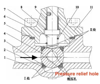
1. Valve body 2. Valve seat 3. Seal ring 4. Ball 5. Winding gasket 6. Valve shaft 7. Screw 8. Thrust washer 9. Bearing 10. Spring 11. Valve bonnet
Figure 1 Cryogenic top-entry floating slope ball valve
Additionally, since the spring is compressed between the valve stem and the ball, it twists and deforms as the valve stem rotates during opening and closing. This reduces the spring's service life, making it prone to malfunction and potentially causing internal leakage.

1. Valve body 2. Valve seat 3. Seal ring 4. Ball 5. Winding gasket 6. Valve shaft 7. Screw 8. Thrust washer 9. Bearing 10. Spring 11. Valve bonnet
Figure 1 Cryogenic top-entry floating slope ball valve
2.2 Cryogenic Top-Entry trunnion ball valve
Cryogenic top-entry trunnion ball valves can be designed to handle high-pressure and large-diameter requirements. The contact pressure between the ball and sealing ring is created by a combination of the horizontal spring force behind the valve seat and the pressure of the medium. To prevent internal leakage under low-pressure conditions, the spring preload must provide enough initial sealing pressure, ensuring a tight fit between the ball and sealing ring after installation. As a result, the structure of a standard top-entry trunnion ball valve is relatively complex, requiring specially designed tools to assemble and disassemble valves of various specifications, which makes assembly, disassembly, and maintenance challenging.
3. Structural Features of Cryogenic Top-Entry Trunnion Slope Ball Valves
To achieve two-way sealing, extend service life, and reduce torque under cryogenic conditions, a structural optimization was implemented based on the design of a standard top-entry floating slope ball valve. The primary structure is illustrated in Figure 2.
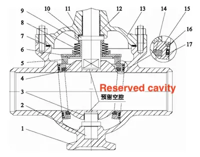
1. Valve body 2. Lower valve shaft 3. Bearing II 4. Ball 5. Pressure ring 6. Pressure plate 7. Gasket 8. Disc spring 9. Bushing 10. Upper valve shaft 11. Thrust washer 12. Bearing I 13. Valve bonnet 14. Sealing ring I 15. Valve seat 16. Sealing ring II 17. Ban seal
Figure 2 Cryogenic top-entry trunnion slope ball valve
3.1 Sphere
The structure of the valve ball is illustrated in Figure 3. Each side of the ball opening features an angled wedge surface, parallel to the inclined surfaces on both the valve body and valve seat assembly. The top surface of the ball is machined with a rectangular tenon groove that aligns with the flat shaft on the lower end of the upper valve shaft. The bottom surface of the ball includes a small step within the shaft hole of sliding bearing 1. The step and the top of the lower valve shaft form a cavity that allows the ball to move vertically. This cavity ensures that the vertical spring can apply sufficient sealing pressure between the ball and the sealing ring, providing the spring with an adjustable range. The eccentricity between the centerline of the ball’s flow channel and the horizontal line of the ball’s center is optimized to minimize flow resistance.
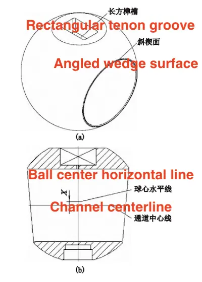
(a) Three-dimensional isometric view (b) Two-dimensional front view
Figure 3 Sphere structure

(a) Three-dimensional isometric view (b) Two-dimensional front view
Figure 3 Sphere structure
3.2 Valve Seat
The valve seat features a two-way sealing structure, offering greater reliability than a floating ball valve, which depends on a single-direction seal from the downstream valve seat. The contact seal between the valve seat and the ball is machined with a notch to install the PCTHE sealing ring I (Figure 2). The rear surface, which contacts the valve body's inclined surface, is also machined with notches for installing the ban plug and PCTFE sealing ring II, providing the valve seat with double sealing.
3.3 Pressure Ring
The upper part of the valve seat and the pressure ring are aligned using the inclined shoulder of the pressure ring (Figure 4). The inner surface of the pressure ring engages with the positioning boss I at the bottom of the pressure plate, ensuring that the spring preload force is transmitted downward through the pressure plate, pressure ring, and valve seat as a unit. This force is then directed to the ball and the slope of the valve body, ensuring a uniform sealing force on the valve seat assembly. This design prevents uneven sealing, which is a common issue in traditional floating ball valves where the spring directly contacts the ball and valve shaft. Additionally, the use of a disc spring eliminates the risk of torsional deformation and failure that may occur in cylindrical coil springs due to the rotation of the valve stem.
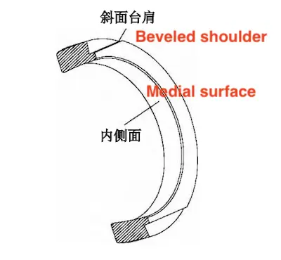
Figure 4 Pressure ring structure

Figure 4 Pressure ring structure
3.4 Pressure Plate
Figure 5 shows the structure of the pressure plate. The upper part features a positioning boss I for installing the spring. The inner hole of the pressure plate is designed to fit the outer diameter of the shaft sleeve, creating a guide space for spring installation. The top of the shaft sleeve contacts the valve shaft shoulder, allowing the shaft sleeve and upper valve shaft to slide the compression spring up and down along the valve shaft axis. A thrust washer and sliding bearing I are positioned on the upper end surface of the valve shaft shoulder.
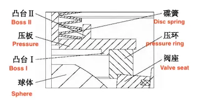
Figure 5 Pressure plate structure

Figure 5 Pressure plate structure
3.5 Valve Body
A conical shape is cast at the front and bottom of the valve body (Figure 6), and a threaded through-hole is machined at the top to connect with the one-way pressure relief valve. This valve allows the discharge of abnormal vaporization pressure from inside the valve cavity to the outside. It addresses the issue of pressure buildup in cryogenic valves, ensuring the safety and reliability of the pipeline system.
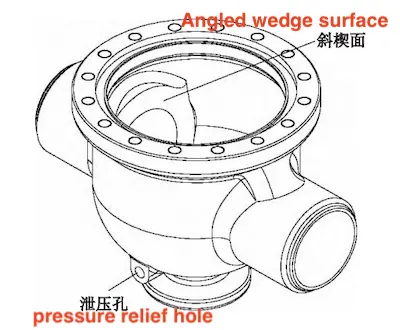
Figure 6 Valve body structure

Figure 6 Valve body structure
4. Valve Body Strain Analysis
When designing a cryogenic top-entry trunnion slope ball valve, initial theoretical calculations should be conducted, including those for valve body wall thickness, sealing pressure, valve torque, valve shaft strength, and the strength of the connecting bolts. To achieve two-way sealing, it is necessary not only to select the appropriate design parameters but also to perform strain analysis on the valve body. This helps determine the optimal structure of the valve body, minimizing deformation of the valve body’s wedge surface and ensuring a proper seal on the back of the valve seat.
4.1 Parameter Setting
Nominal size: DN100
Nominal pressure: PN20
Design temperature: -196 - 60°C
Design pressure: 1.9MPa
Valve body material: CF8M
The specific mechanical properties are shown in Table 1.
Table 1 Mechanical properties parameters of valve body materials
Nominal pressure: PN20
Design temperature: -196 - 60°C
Design pressure: 1.9MPa
Valve body material: CF8M
The specific mechanical properties are shown in Table 1.
Table 1 Mechanical properties parameters of valve body materials
| Parts | Material | Elastic Modulus E (MPa) | Allowable Stress S (MPa) | Tensile Strength Su (MPa) | Yield Strength Sy (MPa) |
| Valve body | CF8M | 2.0 × 10⁵ | 138 | 485 | 205 |
4.2 Boundary Condition Setting
Under low-temperature conditions, the valve body is influenced by the combined effect of the sealing test pressure and the vertical preload force of the spring, with values set at 2.09MPa and 3600 N, respectively. The calculation model of the valve body under testing conditions is shown in Figure 7. Through analysis, it is verified whether the strength of the valve body meets the required standards, and the sealing performance of the back of the valve seat is assessed based on the maximum deformation of the valve body’s wedge surface.
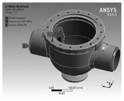
Figure 7 Calculation model under test conditions

Figure 7 Calculation model under test conditions
4.3 Stress Analysis and Evaluation
The valve body is subjected to a stress assessment in accordance with standard requirements. The stress assessment includes only the overall primary membrane stress (σm) and the combined partial membrane stress and primary bending stress (σL + σb). Five evaluation points are selected at or near the maximum stress location of the valve body (Figure 8). After applying the boundary conditions, the software calculates the membrane stress and bending stress in the critical section (Table 2). The calculated stresses are then compared to the standard allowable values to ensure they are within the acceptable limits. Stress concentration occurs at the intersection of the wedge surface and the curved surface of the valve body (Figure 9). Introducing fillets at this location can effectively reduce stress concentration.
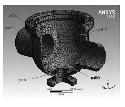
Figure 8 Evaluation path
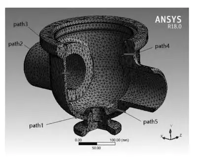
Figure 9 Maximum principal stress distribution
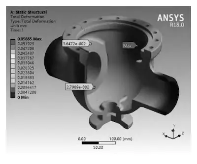
Figure 10 Strain distribution
Table 2 Valve body stress evaluation results

Figure 8 Evaluation path

Figure 9 Maximum principal stress distribution

Figure 10 Strain distribution
Table 2 Valve body stress evaluation results
| Path | σm (MPa) | Calculated value | (σL + σb) (MPa) | Result | ||
| Calculated value | Allowable value 1.25S |
Allowable value 1.875S |
||||
| Valve body | Path 1 | 12.7 | 13.309 | compliance | ||
| Path 2 | 17.562 | 26.588 | compliance | |||
| Path 3 | 0.486 | 172.5 | 20.699 | compliance | ||
| Path 4 | 5.104 | 15.69 | compliance | |||
| Path 5 | 19. 948 | 32.237 | compliance | |||
Based on this design, the valve body wall thickness was optimized, and a final thickness of 10 mm was chosen. A comprehensive strain analysis of the valve body structure was performed (Figure 10). The analysis results indicate that the valve body deformation is minimal, with a maximum deformation of 0.05665 mm, while the maximum deformation of the valve body wedge surface is 0.03647 mm
5. Conclusion
This article presents the structural characteristics of cryogenic top-entry trunnion slope ball valves used in LNG receiving stations, along with the process for their online disassembly, maintenance, and reassembly. SolidWorks 3D modeling software was utilized to create the valve body model, which was then imported into ANSYS finite element analysis software for structural optimization. The wall thickness of the valve body was optimized to minimize deformation while meeting the design requirements for the operating conditions, providing a crucial foundation for future product improvements. This product is currently under patent application for an invention in China, with the application number 202110497848.


