Installation and Construction Process of Valves in Liquefied Natural Gas Plants
On this page
[Abstract] During the construction of large-scale international liquefied natural gas (LNG) plants, there are many types of valves, the processes are complex, and the costs are high. The construction workload accounts for a significant proportion and involves the collaboration of multiple departments and professions, making it difficult to manage. The cost of rework due to material loss is high and time-consuming. Using a liquefied natural gas plant construction project with a steel structure processing capacity of 200,000 tons as an example, the cost of valve construction accounts for more than 10% of the total investment in pipeline-related construction. Therefore, in LNG plant construction projects, it is necessary to establish a detailed valve construction process to guide the collaboration of various disciplines. Beginning with the condition of the valve upon receipt, this paper analyzes its construction process and technical requirements throughout the construction cycle. It establishes the comprehensive valve construction process for LNG plants and improves the efficiency of valve construction management.
Based on material procurement status and construction requirements, valves can be categorized as those requiring both painting and tightness testing, those requiring only painting, those requiring only tightness testing, and those requiring neither painting nor tightness testing. The process flows for these four types of valves vary, and their detailed workflows must be clearly defined to ensure that each valve meets the corresponding technical requirements. Once the valve has been painted and tested for tightness, attention must shift to its installation and maintenance. This article outlines the entire valve construction process, addressing these aspects and analyzing the key technical requirements of each stage.
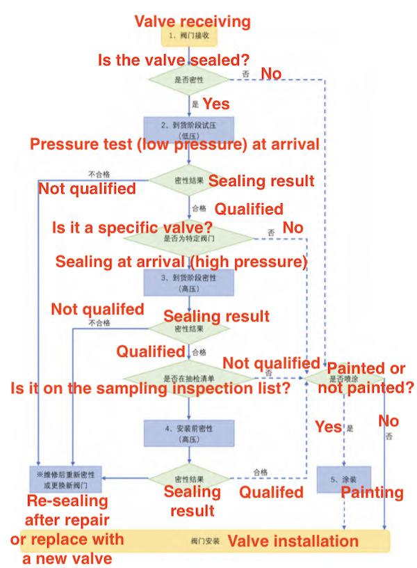
Based on meeting the project specification requirements, the following construction process is formulated according to the valve type, its painting status, and the tightness test results upon arrival, as shown in Figure 1-1.

Figure 1-1 Construction process flow chart of LNG plant valves

Figure 1-1 Construction process flow chart of LNG plant valves
(1) The valve tightness test can be divided into low-pressure and high-pressure tests based on pressure. Generally, a low-pressure test refers to a test where the pressure is P≤1.6MPa, while a high-pressure test refers to a test where the pressure exceeds 1.6MPa. The division between high and low pressure should also be determined according to project requirements and the relevant standards of the construction unit.
(2) Valve tightness tests are divided into watertight and airtight tests based on the sealing medium.
(2) Valve tightness tests are divided into watertight and airtight tests based on the sealing medium.
Different test types have distinct requirements for test equipment, facilities, and construction processes. Therefore, the valve tightness test should carefully consider the test medium (water or gas), test pressure, plugging method, detection method, maintenance method, and other relevant factors. The specific requirements are as follows:
(1) Test medium: For water as the test medium, it is necessary to determine the chlorine content. For valves made of stainless steel or containing stainless steel internal parts, the chlorine content should generally not exceed 2 ppm. The chlorine content for carbon steel valves can follow the drinking water standard. For gas as the medium, both high and low-pressure air tightness tests require calculating the system TNT equivalent during the test to select either hard protection isolation or range isolation. The typical minimum isolation distance for range isolation is 30 meters.
(2) Test pressure and control: The pressure for the tightness test differs from that for the strength test. It is typically provided by the designer and valve manufacturer based on the valve's operating parameters and relevant standards. The test pressure is controlled as shown in Figure 2-1.

Figure 2-1 Pressure rise and fall curve of leak tests
Pt is test pressure, and Pd is design pressure. During engineering construction, appropriate steps for increasing and decreasing pressure should be set based on project requirements to reduce testing and inspection time.
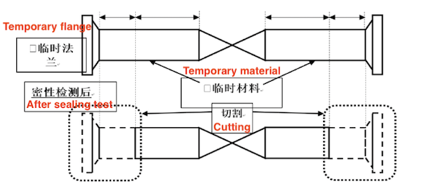
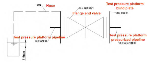
(3) Sealing: Generally divided into welding type, flange type, and test bench clamp type. The project should comprehensively consider equipment and facility capacity and prioritize the use of the test bench clamp method for testing. If welding is used, the cutting margin for removing the plug must be considered. The welding and test bench clamp sealing methods are shown in Figures 2-2 and 2-3. The flange type is similar to the clamp type, except that it requires blind plates and bolts for fixing.

Figure 2-2 Plugging methods of Welded valves

Figure 2-3 Plugging methods of Flange valves
(4) Detection method: Droplet method or bubble method. For high-pressure tightness tests, remote monitoring is required. When the bubble method is used for detecting leaks, the connecting hose should be inserted 3-6 mm below the water surface.
(5) Maintenance: After the watertight test, dry air should be used to blow the inside of the valve until it reaches the dew point value required by the project. Typically, the dew point value must be less than 0°C. Whether airtight or watertight test, the valve cavity must be protected with a desiccant or preservative after the test, and the end face should be coated with anti-corrosion oil and sealed with a plastic pipe cap.
(1) Test medium: For water as the test medium, it is necessary to determine the chlorine content. For valves made of stainless steel or containing stainless steel internal parts, the chlorine content should generally not exceed 2 ppm. The chlorine content for carbon steel valves can follow the drinking water standard. For gas as the medium, both high and low-pressure air tightness tests require calculating the system TNT equivalent during the test to select either hard protection isolation or range isolation. The typical minimum isolation distance for range isolation is 30 meters.
(2) Test pressure and control: The pressure for the tightness test differs from that for the strength test. It is typically provided by the designer and valve manufacturer based on the valve's operating parameters and relevant standards. The test pressure is controlled as shown in Figure 2-1.

Figure 2-1 Pressure rise and fall curve of leak tests
Pt is test pressure, and Pd is design pressure. During engineering construction, appropriate steps for increasing and decreasing pressure should be set based on project requirements to reduce testing and inspection time.
(3) Sealing: Generally divided into welding type, flange type, and test bench clamp type. The project should comprehensively consider equipment and facility capacity and prioritize the use of the test bench clamp method for testing. If welding is used, the cutting margin for removing the plug must be considered. The welding and test bench clamp sealing methods are shown in Figures 2-2 and 2-3. The flange type is similar to the clamp type, except that it requires blind plates and bolts for fixing.

Figure 2-2 Plugging methods of Welded valves

Figure 2-3 Plugging methods of Flange valves
(4) Detection method: Droplet method or bubble method. For high-pressure tightness tests, remote monitoring is required. When the bubble method is used for detecting leaks, the connecting hose should be inserted 3-6 mm below the water surface.
(5) Maintenance: After the watertight test, dry air should be used to blow the inside of the valve until it reaches the dew point value required by the project. Typically, the dew point value must be less than 0°C. Whether airtight or watertight test, the valve cavity must be protected with a desiccant or preservative after the test, and the end face should be coated with anti-corrosion oil and sealed with a plastic pipe cap.
After the valve passes the tightness test, the uncoated valve must be treated with an anti-corrosion coating. The general requirements are as follows:
(1) The valve end and valve stem must be protected before sandblasting.
(2) The spray paint must comply with the project specifications.
(3) After painting is completed, a sign must be attached to indicate the valve type and valve position number.
(4) Ensure the valve's water surface is properly protected during the hoisting process.
Before hoisting large valves, a hoisting plan must be provided, including the valve turning plan and the side-entry or front-installation plan. The plan must consider the bundling method, hanging buckle method, paint protection strategy, tool and crane capacity requirements, positioning method, and hoisting path. The valve manufacturer must provide a hoisting plan for instrument valves equipped with pneumatic or electric actuators.
(1) Before placing the valve, check its internal cleanliness and inspect the valve ends for corrosion. If any issues are found, corrective action is required.
(2) After the valve is hoisted into place, for flange valves, ensure at least one bolt hole is aligned and insert a bolt. If a positioning bolt is present, ensure the valve is centered before inserting it to prevent difficulty in removing the positioning bolt during future disassembly or reinstallation.
(3) Before officially installing the valve, ensure it is properly centered to prevent damage to the valve body during flange connection.
Once the valve is installed, it will remain in a cross-operation environment for an extended period. To prevent damage caused by cross-operations, the following tasks should be performed:
(1) Remove or securely isolate the wear-prone parts.
(2) Protect the valve body and actuator to prevent dust accumulation and corrosion.
(1) Remove or securely isolate the wear-prone parts.
(2) Protect the valve body and actuator to prevent dust accumulation and corrosion.
(1) The valve type, whether the valve has been painted upon arrival, and the results of the valve tightness test should be comprehensively considered to develop the full-process construction procedure for the valve.
(2) The valve tightness test should comprehensively consider the valve type, test medium, and the capabilities of equipment and facilities to complete the test safely and efficiently.
(3) During the valve installation process, the internal and external corrosion of the valve should be inspected, and any unqualified areas should be rectified; proper alignment must be ensured during installation.
(4) The vulnerable parts of the valve should be removed or securely isolated, and the valve body and actuator should be protected to prevent corrosion.


