Designing Ultra-Low Temperature Ball Valves
On this page
2.3 Design of Embedded Closed Groove at the SPE End of Ultra-Low Temperature Ball Valves
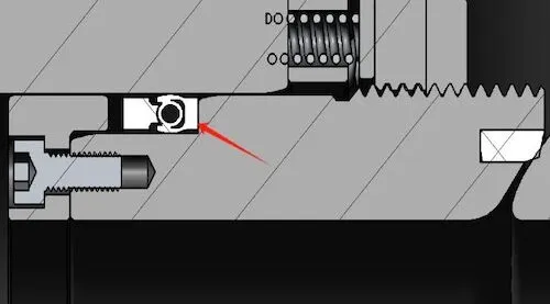
The valve seat sealing position of the fixed cryogenic ball valve differs slightly from that of a normal-temperature valve. Currently, the Lip-seal is commonly used to replace the traditional O-ring sealing structure in normal-temperature valves. The valve seat structure comes in two forms: SPE single piston and DPE double piston. In the design of the common SPE single piston, the Lip-seal is typically mounted on the outer surface of the valve seat support ring, secured with a retaining ring, and then installed into the valve seat box of the body cavity along with the valve seat assembly, as shown in Figure 3. This structure has certain drawbacks in the top-mounted cryogenic ball valve, because during installation, the entire valve seat assembly must be shifted forward and backward to make room for the ball, causing unavoidable friction between the Lip-seal and the inner wall of the valve seat box. Additionally, during installation, since the valve seat assembly and the valve seat box are clearance-fitted, ensuring perfect coaxial alignment is impossible. As a result, when introducing the valve seat assembly, the Lip-seal may become distorted or partially deformed. These potential issues can irreversibly affect the sealing of the Lip-seal, potentially leading to a complete loss of sealing performance.

Figure 3 Common SPE single piston design
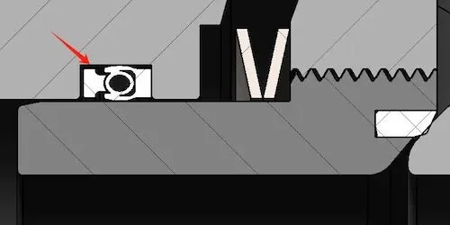
The embedded SPE single-piston design is shown in Figure 4. This design primarily changes the position of the Lip-seal, moving it from the outer circumference of the valve seat support ring to being embedded in the valve body seat box. During assembly, the Lip-seal is first installed into the valve cavity seat box. The groove width is widened by only 0.5 mm beyond the nominal size of the Lip-seal, with an H8 tolerance. Once the Lip-seal is installed in the groove, its forward and backward movement is minimal and can be nearly disregarded. Next, the valve seat assembly is inserted into the valve cavity. During the forward and backward movement of the valve seat assembly, only the inner ring of the Lip-seal and the outer surface of the valve seat support ring experience consistent friction. Compared to the previous design, the Lip-seal does not move within the groove, reducing the risk of distortion and deformation. This indirectly protects the precision sealing performance of the part and enhances overall stability.

Figure 4 Embedded SPE single piston design

Figure 3 Common SPE single piston design
The embedded SPE single-piston design is shown in Figure 4. This design primarily changes the position of the Lip-seal, moving it from the outer circumference of the valve seat support ring to being embedded in the valve body seat box. During assembly, the Lip-seal is first installed into the valve cavity seat box. The groove width is widened by only 0.5 mm beyond the nominal size of the Lip-seal, with an H8 tolerance. Once the Lip-seal is installed in the groove, its forward and backward movement is minimal and can be nearly disregarded. Next, the valve seat assembly is inserted into the valve cavity. During the forward and backward movement of the valve seat assembly, only the inner ring of the Lip-seal and the outer surface of the valve seat support ring experience consistent friction. Compared to the previous design, the Lip-seal does not move within the groove, reducing the risk of distortion and deformation. This indirectly protects the precision sealing performance of the part and enhances overall stability.

Figure 4 Embedded SPE single piston design
2.4 Design of the DPE End
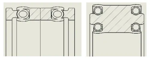
Similar to the SPE end design, the DPE end seal of the low-temperature fixed ball valve also uses a Lip-seal to replace the traditional O-ring seal structure used at room temperature. DPE, unlike SPE, is known as a double-piston structure, and its default design is generally on the rear side of the valve. The design of the DPE side must account for the piston effect on the rear of the valve and the piston effect required for reverse sealing of the valve cavity, preventing it from being made into a closed inner groove structure like the front of the valve. Two common types of DPE double-piston Lip-seal seals are used. The first is a single-spring back-to-back type, as shown in Figure 5(a), featuring two symmetrical single-piston seals on the left and right sides. The second is a double-spring back-to-back type, as shown in Figure 5(b). The difference between this structure and the previous one is that the jacket on each side has two springs symmetrically distributed vertically, and each seal set is inlaid with four springs. Compared to the two, the groove required for the single-spring back-to-back type is relatively narrow. When maintaining the sealing pressure ratio of the middle cavity, the sealing section provided after the valve will be smaller, resulting in a lower corresponding sealing pressure ratio. It is generally used for pressure ranges between 150 lb and 600 lb (within PN100). However, this is not absolute nor stipulated by any standard; it is simply a common practice in the industry. The double-piston structure shown in Figure 5(b) features a relatively wider sealing section. The most common widths are 8 mm, 11.25 mm, 12 mm (Saint-Gobain), and 14 mm. The general design principle is to choose the widest possible section to ensure an appropriate sealing pressure ratio in both forward and reverse directions, while also providing enough space for a larger embedded spring section. Under ultra-low temperature conditions, the spring's effective compression can be ensured without yielding or failure when compressed. A spring that is too small is difficult to control in terms of compression and is easily damaged.

(a) Single spring back-to-back form (b) Double spring back-to-back form
Figure 5 Two common Lip-seal seals for DPE
In addition to the considerations when selecting, the friction between the Lip-seal and other components should also be considered during the design process. Of the two DPE seals shown in Figure 5, the Lip-seal is composed of a PTFE jacket and a nickel-based alloy spring. The sealing principle relies on strict control of the surface finish of the outer circumference of the valve seat support ring and the inner surface of the valve body, as well as precise control of their mechanical tolerances, which are generally at grade 7. When assembling qualified Lip-seal seals, valve seat support rings, and valve chambers, an interference fit is used. After installation, the spring will be compressed by the inner and outer circumferences and become elliptical. At this stage, the spring's deformation remains within the recoverable range.
The reverse extrusion force generated by the spring deformation causes the PTFE outer ring to fit closely against the inner wall of the valve chamber, forming an outer circumference seal. Similarly, the extrusion force in the inward direction causes the inner ring to fit closely against the valve seat support ring, forming an inner circumference seal. In principle, it is similar to an O-ring, as both rely on elastic deformation. The key difference between the two is that when the O-ring undergoes elastic deformation, the extrusion force on the inner and outer circumferences is much smaller than the force generated by the Lip-seal. According to the principle of friction, when the surface finish of the parts is the same, friction (F) = normal force (F) × friction coefficient (μ). For the same part, the same surface finish means the same friction coefficient (μ), so the key factor affecting friction is the normal force, which in this case is the positive extrusion force. Therefore, in the ultra-low-temperature ball valve seat seal, the friction generated by the Lip-seal is much greater than that generated by the O-ring. Thus, when calculating the thrust required for the valve seat, the O-ring calculation method should not be relied upon. Additionally, the normal force here is generated by extrusion, and it cannot be accurately quantified. Therefore, the designer must rely on their experience to determine a reasonable thrust for the valve seat. This thrust must account for sealing the valve seat under full pressure differential conditions as well as initial sealing at low pressure.
Many technicians new to cryogenic ball valves often remark: "The valve seals well at room temperature, but it performs poorly at low temperature." In many cases, this issue is due to improper specific pressure. At low temperatures, the valve seat assembly tightens due to the contraction of the parts. The thrust at normal temperatures is insufficient to push the valve seat, resulting in leakage at the ball port. This phenomenon is particularly pronounced at the DPE end. The sealing ring at the DPE end has two to four times the number of embedded springs compared to the SPE end, and the corresponding friction force increases accordingly, placing higher demands on the design. When designing the DPE end, technicians should thoroughly consider the impact of every detail on the seal to ensure the design's rationality and stability.
3. Conclusion
In general, the design of cryogenic ball valves has evolved from normal temperature ball valves, but there are also many differences between the two. Due to the significant difference in operating temperatures, designers need to pay special attention to material selection, sealing forms, and other factors. The drainage groove design of the extended sleeve can significantly prevent the problem of water packing freezing and damaging the valve stem, while also indirectly reducing the increased switching torque caused by ice wear. For different opening methods, designers can adjust the drainage groove design as long as the same effect is achieved. The composite structure of the stuffing box is relatively popular in foreign markets. Many domestic designs have omitted the Lip-seal component, which can reduce short-term costs. However, in the long term, valves with this sealing ring feature lower torque and longer service life, making them worth promoting. Additionally, the design of single and double pistons is flexible and adaptable. Attention should be given to the influence of friction on thrust formation, which differs significantly from normal temperature valves. The required thrust is greater. Similarly, when the valve is opened, the required torque is slightly higher than that of normal temperature valves.


