Design of Balanced Pipeline Plug Valves
On this page
A pipeline plug valve is a cut-off valve used for long-distance natural gas pipelines and station control systems, capable of meeting the special requirements of natural gas pipelines. The valve must possess special technical properties, such as suitability for harsh working conditions, a service life of over 30 years, two-way zero leakage, fireproof and anti-static features, resistance to acidic medium corrosion, and labor-saving operation. The technical standards followed by pipeline plug valves include API 6D pipeline valves for oil and gas industry pipeline transportation systems and API 599 flange and welded metal plug valves. Currently, the plug valves used in China’s natural gas pipelines and station control systems are all imported inverted balanced oil-sealed plug valves. The development, promotion, and application of locally produced pipeline plug valves in long-distance natural gas pipeline systems play an important role.

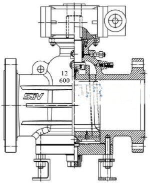
Figure 1 Pipeline balanced plug valves

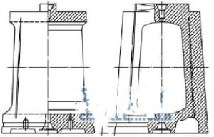
Figure 2 Plugs
The pipeline balance plug valve (Figure 1) adopts an inverted plug (Figure 2) with a pressure-balanced oil seal structure. The valve consists of a valve body, valve stem, plug, bottom cover, coupling balance ring, preload spring, plug adjustment rod, bottom cover seal adjustment gasket, grease injection valve, valve stem seal assembly, and other components. The bottom seal adjustment gasket is compressed by the bottom cover to achieve complete isolation of the valve body cavity from the outside environment, ensuring reliable sealing and no leakage. An adjusting screw with a protective cover is installed on the bottom valve cover, allowing easy adjustment of the plug position and pre-tightening of the sealing pair. The valve can be equipped with pneumatic, electric, or hydraulic actuators as needed. The plug surface is hardened and features a special oil tank circuit. There are double sealing grease injection devices outside the valve body: one for achieving emergency sealing of the valve stem by injecting grease, and the other for injecting grease into the upper cavity of the valve body. The small end of the conical plug body is connected to the valve stem through a balance ring, with an adjustment support installed on the valve cover at the bottom of the valve body to adjust the position of the plug. The valve adopts a fireproof design, includes an electrostatic lead-out device, and the flow channel features full-diameter, regular, and Venturi holes. The valve material can be carbon steel, low-temperature steel, stainless steel, or alloy steel. The drive modes include electric, pneumatic, and manual.
The pipeline pressure-balanced plug valve connects or disconnects the channel port on the plug with the channel port on the valve body by rotating the valve stem 90 degrees to open or close the valve. Sealing grease is injected through the grease injection valve located on the upper part of the valve cavity. The grease is evenly applied to the sealing surface through the special oil groove on the surface of the plug, under the action of injection pressure, forming a dense oil film layer to achieve bidirectional sealing of the valve and lubricate the sealing surface. A small flow hole is opened at the large end of the plug, allowing the pipeline medium to enter the bottom of the plug. The plug is pushed upward and close to the inverted cone surface of the valve body by the force of the medium from the bottom. A one-way valve is installed at the small end of the plug. When the grease injection pressure at the top of the valve cavity is higher than the pipeline medium pressure, the one-way valve closes. When the grease pressure at the top of the valve cavity is lower than the medium pressure, the pipeline medium enters the upper cavity of the valve body through the one-way valve to supplement the grease pressure. At the same time, the plug is balanced with the upward thrust of the medium from the bottom of the plug under the grease pressure in the upper cavity and the gravity of the plug, which can greatly reduce the sealing pressure ratio of the sealing surface, reduce the valve operating torque, and extend the valve's service life. Compared to ordinary sleeve plug valves, pipeline pressure-balanced plug valvess are characterized by small torque, good sealing performance, long service life, wide application range, and adjustable plug position.
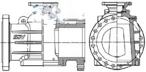
The valve body (Figure 3) is integrally cast with an inverted bell structure, which has high strength, good rigidity, and uniform force. The mass center of gravity of the valve body and valve is essentially coincident with the center of gravity of the pipeline, ensuring good operational stability. The wall thickness of the valve body is calculated and optimized using finite element analysis. The sealing cone surface of the valve body is processed through high-speed fine grinding, achieving a surface roughness accuracy of less than Ra 0.18 μm.

Figure 3 Valve body
The plug is produced through inverted integral forging, achieving a surface roughness of Ra 0.14 μm after precision machining and grinding. The surface hardness of the plug is improved using surface treatment methods such as nitriding, nickel-phosphorus alloy plating, or spraying hard alloy. The surface hardness of supersonic sprayed hard alloy can reach more than 65 HRC, while the surface hardness of nickel-phosphorus alloy plating and heat treatment can reach 58-60 HRC. It possesses superior wear resistance under oil film lubrication. A check valve is located on the upper part (small end) of the plug cone to compensate for the oil injection pressure in the upper part of the valve cavity. A balance hole on the lower part (large end) of the plug introduces medium pressure into the bottom of the plug.
The sealing pair of the pipeline pressure-balanced plug valves uses a metal seal and grease-filled sealing structure. The sealing grease prevents solid particles in the medium from entering the sealing surface, providing excellent protection. The lubrication of the grease reduces the valve operating torque and makes operation labor-saving. The special asymmetric oil groove design on the plug surface automatically fills with sealing grease without leakage when the plug is turned, ensuring oil film integrity and reliable sealing. This asymmetric oil groove design minimizes oil loss, extending the filling time and service life of the grease. The conical seal increases the sealing contact area, ensuring a lubricated oil film and long service life.
The strength and sealing performance of the valve stem are key factors affecting the valve's operation and overall performance. The force on the valve stem mainly comes from packing friction, operating torque, and medium thrust. The valve stem and plug use a slip ring connection method, reducing concentricity error between the valve stem center and the plug cone surface, improving the force condition and operating performance. The valve stem features an anti-slip design, and the packing seal can be replaced online. The valve stem seal uses a triple seal design comprising fireproof packing, an O-ring, and sealing grease. After machining, the surface roughness of the valve stem can reach Ra 0.14 μm, fully meeting the low leakage requirements of the valve stem seal, ensuring reliable long-term operation without needing tightening and maintenance. The valve stem is integrally forged from 4140 and tempered, providing high strength and good toughness. The surface of the valve stem is nitrided or nickel-phosphorus alloy plated, providing high surface hardness and resistance to friction and wear.
The bottom valve cover is the pressure-bearing part at the bottom of the valve and also serves as the fixing and installation support for the bottom sealing gasket and the bottom adjusting rod, requiring high rigidity and strength. Its design and manufacturing follow the ASME specification requirements for flange covers. The bottom valve cover seal uses a fully isolated structure with an integral sealing gasket, ensuring a reliable seal and the tightening force of the valve cover bolts. The adjusting rod installed at the bottom of the valve cover uses a built-in structure. After the adjustment is completed, tighten the gland to ensure zero leakage. The bottom adjustment rod supports the plug and dissipates static electricity generated by the plug.
After the completion of the West-East Gas Pipeline 1, a large number of pipeline oil seal plug valvess were imported into China, encouraging valve manufacturing companies to develop this product. By continuously absorbing new foreign technologies, the oil seal plug valves has been consistently improved. The new generation of oil-sealed plug valves achieves two-way zero leakage, good sealing performance, safe and reliable use, low valve torque, labor-saving operation, oil film lubrication without wear, long service life, and can be widely used in natural gas pipelines and station control systems.


