Analysis of Corrosion of Plug Valve Lining
The reasons for the damage to the inner liner when the ordinary PTFE-lined plug valve is used in the self-circulation pipeline of the synthesis reactor of the acetic acid system were analyzed, and the performance and characteristics of the T475 were introduced. Using T475 to replace the original ordinary PTFE inner liner and the method of changing the internal structure of the plug valve was discussed in this article.
1. Overview
There are strict requirements on temperature on the self-circulation pipeline of the synthesis reactor of the 300,000-ton acetic acid production plant. To achieve the proper operation effect, the temperature of this circulation pipeline is generally controlled at 185 to 195°C, and the pressure is controlled at 218 to 410MPa. Most of the pipelines use ordinary PTFE-lined plug valves. When the system was shut down for maintenance after working for 2 to 3 months, it was found that the valves could not be closed well, and proper process treatment could not be performed. The main reason is that the inner lining of the plug valve has fallen to some extent, and more seriously, there is tearing.
2. The analysis for the failure
(1) The cold flow causes the lining to fall.
At room temperature, solids such as plastics, rubber, and metals are deformed under load, and the deformation that cannot return to the original shape after the load is removed is called cold flow. Cold flow is common to be seen in lined plug valves, especially special lined plug valves used in acetic acid process conditions. Dedicated valves are generally purchased in the early stage of infrastructure construction due to their long order cycles, and sometimes they are stored for half a year. When the valve is installed on the system, the lining may be stressed due to storage. When the stress is removed, it cannot return to its original state, resulting in deformation. On the one hand, the solution to this is to pay attention to keeping the lining material free from any stress when the valve is stored. Keep the flow channel of the plug valve clean and smooth, and use non-metallic plates such as wood and plastic to block the inlet and outlet of the plug valve, so that it forms a closed environment. On the other hand, it is required to keep the plug, lining and valve body in close contact to prevent the lining from being deformed due to external force.
(2) Unstable operation leads to misalignment of the lining.
Since the plug valve is often opened or closed during the operation of the system, and the valve used on this circulation pipeline is a large-diameter valve, generally 8 or 10 inches, this will cause too great friction force on the lining and the plug. When the operator cannot evenly apply force for the plug when rotating the handwheel, it may cause misalignment between the plug and the lining, resulting in a high flow rate, large flow and high-temperature liquid scouring the lining material, and a large amount of medium accumulating between the lining and the valve body, causing the lining to gradually fall from the valve body. Therefore, the uniform force with an extension rod or F-type wrench during operation can reduce the misalignment or damage to the lining due to uneven force.
(3) Partial opening of the valve leads to deformation of the lining
At the initial stage of start-up, the system is in the trial run and debugging stage, and cannot reach full-load operation immediately. The flow rate must be controlled by adjusting the opening of the valve. Self-adjusting globe valves are often adopted for flow adjustment. On the one hand, the data can be directly reflected in the control room, which is beneficial for the control personnel to operate. On the other hand, it can ensure that there is no one on-site during system debugging to ensure safety. The plug valve is mainly used for cutting, not for flow regulation. However, the system fluctuates frequently at the initial stage of start-up, and if the system temperature and flow are only controlled by the self-adjusting globe valve, it cannot play the role of slight adjustment. Therefore, the control room and on-site personnel can only cooperate to make fine adjustments by adjusting the opening of the plug valve, which leads to the situation that the plug valve is half open and half closed.
When the plug valve is in the fully open state, the plug and valve body completely wrap the inner liner, and it is not in contact with the medium. When the plug valve is in the fully closed state, the plug isolates the medium from the lining, and the lining does not come into contact with the medium. This is the correct way to use the plug valve, and it can also prolong the service life of the valve. However, limited by conditions, the plug valve is often in a partially open state (Figure 1a), and the process medium is constantly flushing the plug valve lining. However, the system is in an unstable stage at the initial stage of driving, and the constant changes in temperature, pressure and flow rate make the lining subject to irregular alternating stress. Ordinary PTFE lining is soft, which will be deformed under alternating stress, and affect its service life. With the extension of the service life of the plug valve, the lining at the valve inlet is detached from the valve body due to scouring and deformation of the medium (Figure 1b).
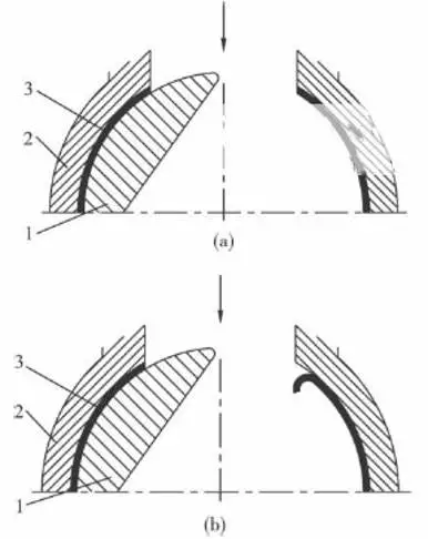
1. Plugs 2. Valve bodies 3. Lining
(a) The plug valve is partially opened. (b) The liner falls off.
Figure 1 The working status of the valve
(4) The thermal expansion of the inner lining causes the plug to fall when it rotates.
There are two reversible transitions in PTFE crystal at 19°C and 30°C. The first transformation is that the PTFE crystal changes from a triclinic system to a hexagonal system, and the volume increases by about 112%. The second transition is that the PTFE crystal relaxes again at 30°C, and the C-C chain helix becomes randomly wound; the volume change at 30°C is about 10% of that at 19°C. During the process of crystal transformation and crystal relaxation, the volume of PTFE changes significantly, which has a certain impact on the application of ordinary PTFE linings.
1. Plugs 2. Valve bodies 3. Lining
(a) The lining expands when heated. (b) The edge of the lining is sheared.
Figure 2 Lining working in a hot state
Since the working temperature of the plug valve exceeds the two temperature expansion points of 19°C and 30°C, thermal expansion deformation will occur when the plug valve is in normal working condition (Figure 2a). When the valve is closed, the plug will form a certain shear force with the lining, causing the lining to deform. With the further rotation of the cock, the excessive shear force is likely to shear the lining material at the edge of the plug valve (Figure 2b), which is also an important cause of internal leakage of the plug valve.
(5) The performance of PTFE decreases due to the increase in temperatures.
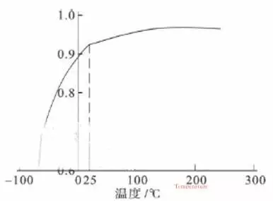
The tensile strength of PTFE gradually decreases with the increase in temperature, with about 100°C as the inflection point. When the temperature is less than 100°C, the change gradient of the tensile strength is greater than that when the temperature is higher than 100°C (Figure 3a). The ultimate nominal strain of PTFE is an increasing convex function of temperatures. The variation of the ultimate nominal strain is approximately bounded by 25°C. When the temperature is less than 25℃, the ultimate nominal strain increases linearly with the increase in temperatures. When the temperature is greater than 25°C, the ultimate nominal strain is hardly affected by temperature. This shows that the PTFE has low elongation and high strength at low temperatures, and high elongation and low strength at high temperatures (Figure 3b). The elastic modulus of PTFE decreases with the increase in temperature. The main reason is that as the temperature gradually increases, the binding force between molecules gradually weakens (Figure 3c).
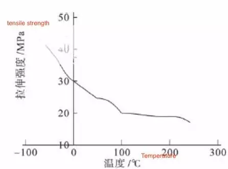
(a) Changes in temperature-tensile strength
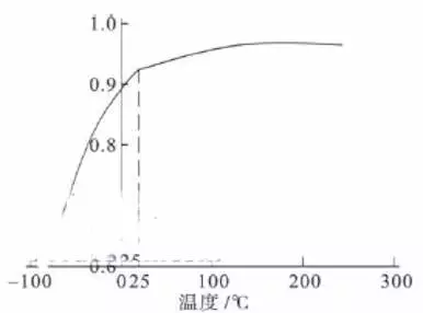
(b) Changes in temperature-limit nominal strain
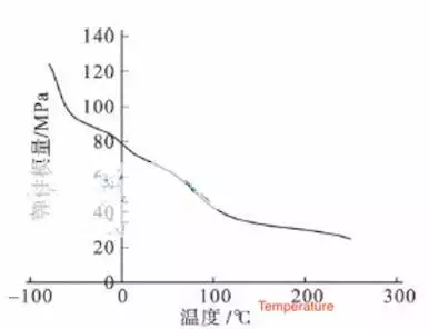
(c) Changes in temperature and elastic modulus
Figure 3 Properties of PTFE
1. Overview
There are strict requirements on temperature on the self-circulation pipeline of the synthesis reactor of the 300,000-ton acetic acid production plant. To achieve the proper operation effect, the temperature of this circulation pipeline is generally controlled at 185 to 195°C, and the pressure is controlled at 218 to 410MPa. Most of the pipelines use ordinary PTFE-lined plug valves. When the system was shut down for maintenance after working for 2 to 3 months, it was found that the valves could not be closed well, and proper process treatment could not be performed. The main reason is that the inner lining of the plug valve has fallen to some extent, and more seriously, there is tearing.
2. The analysis for the failure
(1) The cold flow causes the lining to fall.
At room temperature, solids such as plastics, rubber, and metals are deformed under load, and the deformation that cannot return to the original shape after the load is removed is called cold flow. Cold flow is common to be seen in lined plug valves, especially special lined plug valves used in acetic acid process conditions. Dedicated valves are generally purchased in the early stage of infrastructure construction due to their long order cycles, and sometimes they are stored for half a year. When the valve is installed on the system, the lining may be stressed due to storage. When the stress is removed, it cannot return to its original state, resulting in deformation. On the one hand, the solution to this is to pay attention to keeping the lining material free from any stress when the valve is stored. Keep the flow channel of the plug valve clean and smooth, and use non-metallic plates such as wood and plastic to block the inlet and outlet of the plug valve, so that it forms a closed environment. On the other hand, it is required to keep the plug, lining and valve body in close contact to prevent the lining from being deformed due to external force.
(2) Unstable operation leads to misalignment of the lining.
Since the plug valve is often opened or closed during the operation of the system, and the valve used on this circulation pipeline is a large-diameter valve, generally 8 or 10 inches, this will cause too great friction force on the lining and the plug. When the operator cannot evenly apply force for the plug when rotating the handwheel, it may cause misalignment between the plug and the lining, resulting in a high flow rate, large flow and high-temperature liquid scouring the lining material, and a large amount of medium accumulating between the lining and the valve body, causing the lining to gradually fall from the valve body. Therefore, the uniform force with an extension rod or F-type wrench during operation can reduce the misalignment or damage to the lining due to uneven force.
(3) Partial opening of the valve leads to deformation of the lining
At the initial stage of start-up, the system is in the trial run and debugging stage, and cannot reach full-load operation immediately. The flow rate must be controlled by adjusting the opening of the valve. Self-adjusting globe valves are often adopted for flow adjustment. On the one hand, the data can be directly reflected in the control room, which is beneficial for the control personnel to operate. On the other hand, it can ensure that there is no one on-site during system debugging to ensure safety. The plug valve is mainly used for cutting, not for flow regulation. However, the system fluctuates frequently at the initial stage of start-up, and if the system temperature and flow are only controlled by the self-adjusting globe valve, it cannot play the role of slight adjustment. Therefore, the control room and on-site personnel can only cooperate to make fine adjustments by adjusting the opening of the plug valve, which leads to the situation that the plug valve is half open and half closed.
When the plug valve is in the fully open state, the plug and valve body completely wrap the inner liner, and it is not in contact with the medium. When the plug valve is in the fully closed state, the plug isolates the medium from the lining, and the lining does not come into contact with the medium. This is the correct way to use the plug valve, and it can also prolong the service life of the valve. However, limited by conditions, the plug valve is often in a partially open state (Figure 1a), and the process medium is constantly flushing the plug valve lining. However, the system is in an unstable stage at the initial stage of driving, and the constant changes in temperature, pressure and flow rate make the lining subject to irregular alternating stress. Ordinary PTFE lining is soft, which will be deformed under alternating stress, and affect its service life. With the extension of the service life of the plug valve, the lining at the valve inlet is detached from the valve body due to scouring and deformation of the medium (Figure 1b).

1. Plugs 2. Valve bodies 3. Lining
(a) The plug valve is partially opened. (b) The liner falls off.
Figure 1 The working status of the valve
(4) The thermal expansion of the inner lining causes the plug to fall when it rotates.
There are two reversible transitions in PTFE crystal at 19°C and 30°C. The first transformation is that the PTFE crystal changes from a triclinic system to a hexagonal system, and the volume increases by about 112%. The second transition is that the PTFE crystal relaxes again at 30°C, and the C-C chain helix becomes randomly wound; the volume change at 30°C is about 10% of that at 19°C. During the process of crystal transformation and crystal relaxation, the volume of PTFE changes significantly, which has a certain impact on the application of ordinary PTFE linings.

1. Plugs 2. Valve bodies 3. Lining
(a) The lining expands when heated. (b) The edge of the lining is sheared.
Figure 2 Lining working in a hot state
Since the working temperature of the plug valve exceeds the two temperature expansion points of 19°C and 30°C, thermal expansion deformation will occur when the plug valve is in normal working condition (Figure 2a). When the valve is closed, the plug will form a certain shear force with the lining, causing the lining to deform. With the further rotation of the cock, the excessive shear force is likely to shear the lining material at the edge of the plug valve (Figure 2b), which is also an important cause of internal leakage of the plug valve.
(5) The performance of PTFE decreases due to the increase in temperatures.
The tensile strength of PTFE gradually decreases with the increase in temperature, with about 100°C as the inflection point. When the temperature is less than 100°C, the change gradient of the tensile strength is greater than that when the temperature is higher than 100°C (Figure 3a). The ultimate nominal strain of PTFE is an increasing convex function of temperatures. The variation of the ultimate nominal strain is approximately bounded by 25°C. When the temperature is less than 25℃, the ultimate nominal strain increases linearly with the increase in temperatures. When the temperature is greater than 25°C, the ultimate nominal strain is hardly affected by temperature. This shows that the PTFE has low elongation and high strength at low temperatures, and high elongation and low strength at high temperatures (Figure 3b). The elastic modulus of PTFE decreases with the increase in temperature. The main reason is that as the temperature gradually increases, the binding force between molecules gradually weakens (Figure 3c).

(a) Changes in temperature-tensile strength

(b) Changes in temperature-limit nominal strain

(c) Changes in temperature and elastic modulus
Figure 3 Properties of PTFE


